

01
Choose a Logic Gate Simulator gate
Start with AND, OR, or NOT, then compare NAND, NOR, XOR, and XNOR. Keep the selected gate visible while you change the inputs.
- Use 0 and 1 as LOW and HIGH
- Start with one gate before chaining
Free Logic Gate Simulator
Logic Gate Simulator helps students, teachers, and electronics beginners choose AND, OR, NOT, NAND, NOR, XOR, or XNOR gates, switch 0/1 inputs, see the output instantly, and build a small multi-gate circuit with live explanations.
Built for quick Logic Gate Simulator practice before digital logic homework, electronics class, or a hardware lab.
Start Logic Gate Simulator here: choose a gate, toggle A and B between 0 and 1, inspect the highlighted truth table row, then drag gates into a simple circuit chain.
Use one gate for a clean truth table, or switch to the circuit builder for chained gates.
Click each input to switch between 0 and 1. NOT uses input A only.
Click a gate for the current mode, or drag it onto the circuit builder.
Share the clean page, or copy a result link that includes the selected gate, inputs, and circuit.
Single-gate Logic Gate Simulator



 XOR
XOR 
The highlighted row matches your current inputs.
Use these symbols to connect the gate to Boolean algebra.
Drag-and-drop Logic Gate Simulator
Drop gates to chain them. Each gate receives the previous output plus a selected second input when needed.
Input A1 Input B0 Final output1 Drop AND, OR, NOT, NAND, NOR, XOR, or XNOR here to build a simple circuit.
| A | B | OUT |
|---|
This table recalculates the final output for every A/B input pair.
Multiple conditions must be true at the same time, such as an enable signal and a safety check.
Any one condition can trigger an action, such as either button starting an alert.
A signal is inverted, such as turning an active-high signal into active-low logic.
Two inputs are compared to detect whether they are different, which is useful in adders and parity checks.
Continue from Boolean logic into digital inputs, outputs, voltage, current, and resistance.
Quick check
AND inputs 1 and 0: what is the output?
OR inputs 0 and 0: what is the output?
Which gate outputs 1 when two inputs are different?
NOT input 1: what is the output?
What is the relationship between NAND and AND?
Logic Gate Simulator is an educational Boolean logic model. It explains ideal logic gates and truth tables, not voltage timing, propagation delay, or physical chip behavior.
Logic Gate Simulator starts with clear single-gate results, then moves into a simple drag-and-drop circuit so the same 0/1 logic stays visible.
Choose AND, OR, NOT, NAND, NOR, XOR, or XNOR and Logic Gate Simulator highlights exactly which truth table row explains the current output.

Drag multiple gates into Logic Gate Simulator to build a small circuit chain, then watch the output, step explanation, and circuit truth table update together.
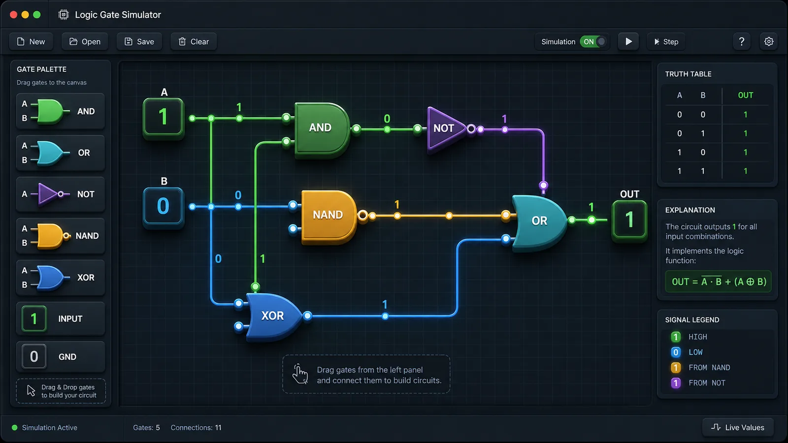
Use this Logic Gate Simulator guide to connect a gate symbol, binary inputs, truth table rows, and the final output explanation.
Start with AND, OR, or NOT, then compare NAND, NOR, XOR, and XNOR. Keep the selected gate visible while you change the inputs.
Toggle A and B and watch the highlighted row move. The highlighted row is the reason the output becomes 0 or 1.
Switch to circuit mode, drag several gates into the canvas, choose each second input, and read the step-by-step explanation.
For homework practice, predict the final output first, then use the circuit truth table to check your reasoning.
Read FAQThese Logic Gate Simulator features make Boolean logic easier to inspect than a static diagram.
Switch A or B and see the 0/1 output update immediately for the selected gate.
Drag AND, OR, NOT, NAND, NOR, XOR, and XNOR into a small circuit builder.
Read plain-language explanations for why the selected inputs create the output.
Use highlighted rows and circuit-level truth tables to verify every input pair.
Copy a result link that preserves the selected gate, inputs, and circuit chain.
Open a browser-friendly logic lab without installing electronics software.
Logic Gate Simulator works well whenever the goal is fast digital logic practice with visible reasoning.
Practice truth tables, Boolean outputs, and chained logic before quizzes or labs.
LearningDemonstrate why each input combination produces a specific result in class.
ClassroomSketch a tiny multi-gate idea before moving to a breadboard or hardware description language.
CircuitCompare AND versus NAND, OR versus NOR, XOR, and XNOR in one screen.
ReviewAfter Logic Gate Simulator, try another free browser simulator for science, math, circuits, or fast shareable practice.
Calculate the final exam score you need, test weighted course modules, and compare 70, 80, 90, and 100 scenarios.

Enter current GPA, completed credits, target GPA, and semester courses to compare A/B/C GPA scenarios.

Choose a 30 second, 1 minute, or 3 minute typing test to track WPM, accuracy, errors, backspaces, and progress.

Practice traffic signs, right-of-way, hazards, parking rules, and mock exam questions with instant explanations.

Practice car diagnostic trouble codes, live data, freeze frames, misfires, no-start cases, inspection order, repair cost, and scoring.

Allocate daily study time by exam date, subject difficulty, mastery, target score, remaining content, pressure, and completion probability.

Choose dice count, sides, modifier, target, comparison, advantage, disadvantage, rerolls, and exploding dice to calculate success odds, average result, range, and distribution.

Enter attackers, hit rate, damage dice, critical rules, defense, armor, hit points, and rounds to estimate damage, kill odds, survival odds, expected rounds, and tactic win chance.

Fast answers about Logic Gate Simulator gates, truth tables, circuit building, sharing, and learning scope.
Yes. Logic Gate Simulator runs in the browser and can be used without an account or installation.
Logic Gate Simulator supports AND, OR, NOT, NAND, NOR, XOR, and XNOR gates with binary 0/1 inputs.
Yes. Single-gate mode highlights the active truth table row, and circuit mode recalculates a final truth table for all A/B input pairs.
Yes. The circuit builder lets you drag multiple gates into a simple chain and choose the second input for two-input gates.
No. Logic Gate Simulator teaches ideal Boolean behavior. It does not simulate voltage levels, propagation delay, fan-out, or physical chip limits.
Open Logic Gate Simulator, choose a gate, switch A and B between 0 and 1, and see the output, explanation, and truth table immediately.
Then switch to Logic Gate Simulator circuit mode to drag multiple gates and test a simple digital logic chain.
Free browser tool. No install required.