Free Thermocouple Simulator

Thermocouple Simulator see signal, cold junction compensation, polarity, and faults in one tool

Thermocouple Simulator combines a signal simulator, cold junction compensation simulator, polarity simulator, fault simulator, and reading error simulator for general thermocouple learning and typical Type K troubleshooting practice.

Runs locally in your browser with a simplified trend model, limited presets, and no device connection.

Thermocouple Simulator interactive Type K bench

Start Thermocouple Simulator here: drag hot junction and cold junction temperature, switch wiring and compensation modes, then compare signal strength, display temperature, error trend, likely cause, and troubleshooting steps.

This simulator runs locally in your browser. It is for learning and troubleshooting practice, not for instrument calibration or safety-critical measurement.

This simulator runs locally in your browser. It is for learning and troubleshooting practice, not for instrument calibration or safety-critical measurement.

Thermocouple Simulator controls

Use the sliders and modes to model a simplified Type K thermocouple trend, not a precision millivolt lookup table.

Thermocouple Simulator presets

Share Thermocouple Simulator

Share the clean page or copy a result link only when you choose to preserve this setup.

Thermocouple signal path

Correct measurement

stable trend
Hot junction 250 °C
Cold junction 25 °C
Instrument 250 °C
Simplified signal 9.23 mV
Cold junction compensation on

Hot end

250 °C

Cold end

25 °C

Signal strength

medium

Instrument display

250 °C

Thermocouple Simulator result details

Temperature difference direction

Hot end is warmer

Reading error trend

Near correct

Wiring state

Normal wiring

Compensation state

Cold junction compensation on

Current fault hint

No obvious simulated fault

With normal polarity and cold junction compensation on, the instrument adds the cold junction reference back to the thermocouple temperature difference, so the displayed value follows the hot end.

Suggested troubleshooting steps

Use these Thermocouple Simulator steps as practice prompts, not as a final equipment diagnosis.

    Boundary: Thermocouple Simulator does not create calibration certificates, uncertainty budgets, safety compliance judgments, brand databases, PLC/DAQ links, compatibility checks, precision millivolt tables, or hundreds of standard reference points.

    Thermocouple Simulator signal workflow

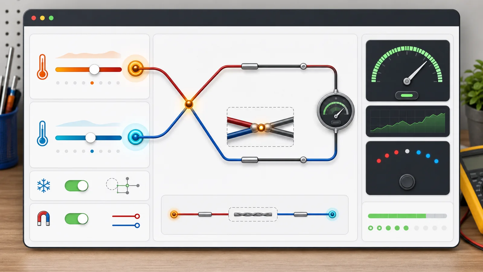
    Thermocouple Simulator makes the hot junction, cold junction, polarity, wiring path, compensation mode, and meter display visible on one learning screen.

    Thermocouple Simulator hot and cold junction model

    Move hot and cold junction temperatures to see why a thermocouple responds to temperature difference and why the Type K signal is tiny.

    Thermocouple Simulator dashboard with hot junction, cold junction, compensation, polarity, and reading trend controls

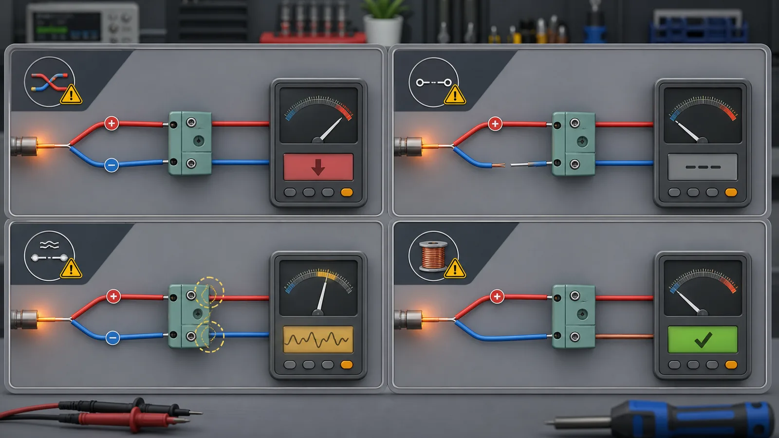
    Thermocouple Simulator fault and reading error view

    Switch reversed polarity, open circuit, loose contact, no compensation, or copper extension mistakes to compare high, low, reverse, and unstable readings.

    Thermocouple Simulator fault panels for reversed polarity, open probe, loose contact, and wrong copper extension

    Thermocouple Simulator quick guide

    Use this Thermocouple Simulator guide to practice the relationship between temperature difference, cold junction compensation, polarity, and common reading errors.

    01

    Set temperatures in Thermocouple Simulator

    Start with the correct measurement preset, then drag hot junction and cold junction temperature to watch signal strength and display temperature change.

    • Use moderate Type K examples before extreme temperatures
    • Notice that the signal follows the difference between junctions
    Open simulator
    02

    Switch Thermocouple Simulator wiring modes

    Compare normal wiring, reversed leads, open circuit, intermittent contact, and wrong copper extension without splitting the task into separate tools.

    • Reversed polarity can make the display move the wrong way
    • Loose contact is modeled as unstable rather than simply high or low
    See features
    03

    Interpret Thermocouple Simulator results

    Read the display temperature, error trend, fault hint, reason, and suggested checks while remembering that the model is for learning only.

    Real troubleshooting still needs the instrument manual, safe measurements, correct extension wire, and a reference method when accuracy matters.

    Read FAQ

    Thermocouple Simulator features

    Thermocouple Simulator merges signal, compensation, polarity, fault, and reading error practice into one pure front-end experience.

    Thermocouple Simulator Type K trend model

    Uses a simplified microvolt-per-degree trend for learning instead of a precision standard table.

    Adjust temperatures

    Thermocouple Simulator cold junction compensation

    Turn compensation on or off to see why the cold end temperature must be accounted for.

    Toggle CJC

    Thermocouple Simulator polarity view

    Reverse positive and negative leads to see why the displayed temperature can move backward.

    Reverse leads

    Thermocouple Simulator fault practice

    Compare open circuit, loose contact, and copper extension mistakes on the same screen.

    Try faults

    Thermocouple Simulator troubleshooting steps

    Get likely causes and checks without claiming the probe is certainly damaged.

    Read steps

    Thermocouple Simulator offline sharing

    Copy a result link explicitly; normal use stays on the clean page and never uploads inputs.

    Share setup

    Thermocouple Simulator learning use cases

    Thermocouple Simulator is built for concept practice, classroom demos, and troubleshooting rehearsal before touching real equipment.

    Thermocouple Simulator for students

    Connect Seebeck signal, junction temperature, and display behavior with interactive controls.

    Study
    Practice now

    Thermocouple Simulator for technicians

    Rehearse why reversed polarity, disabled CJC, loose terminals, and extension wire errors look different.

    Practice
    Compare faults

    Thermocouple Simulator for teachers

    Show multiple thermocouple errors in one tool without separate signal, CJC, polarity, or fault pages.

    Classroom
    Teach concept

    Thermocouple Simulator for boundaries

    Explain why calibration, uncertainty, compliance, PLC links, and exact millivolt tables need real data.

    Scope
    Read limits

    Related tools after Thermocouple Simulator

    After Thermocouple Simulator, continue with other science and electronics simulators for signals, circuits, and measurement thinking.

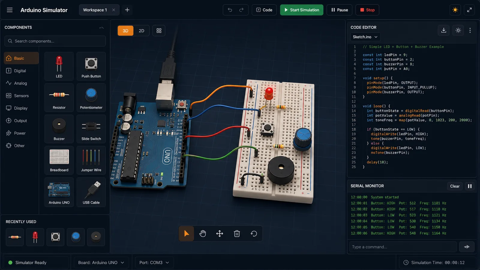
    Arduino Simulator

    Drag LED, resistor, button, potentiometer, and buzzer parts into a browser circuit and run beginner Arduino sketches.

    Arduino Simulator preview showing the browser circuit workspace, code panel, and serial monitor
    Open simulator

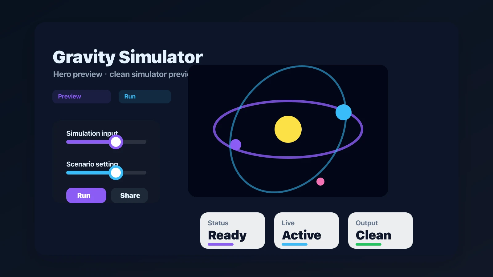
    Gravity Simulator

    Drop planets, stars, and black holes into an N-body physics sandbox with shareable presets.

    Gravity Simulator preview showing the browser simulator interface and result
    Open simulator

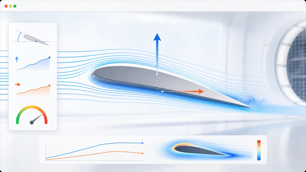
    Airfoil Simulator

    Set angle of attack, air speed, wing area, air density, and airfoil shape to estimate lift, drag, lift-to-drag ratio, and stall risk.

    Airfoil Simulator preview showing airflow streamlines, airfoil controls, lift, drag, and stall risk
    Open simulator

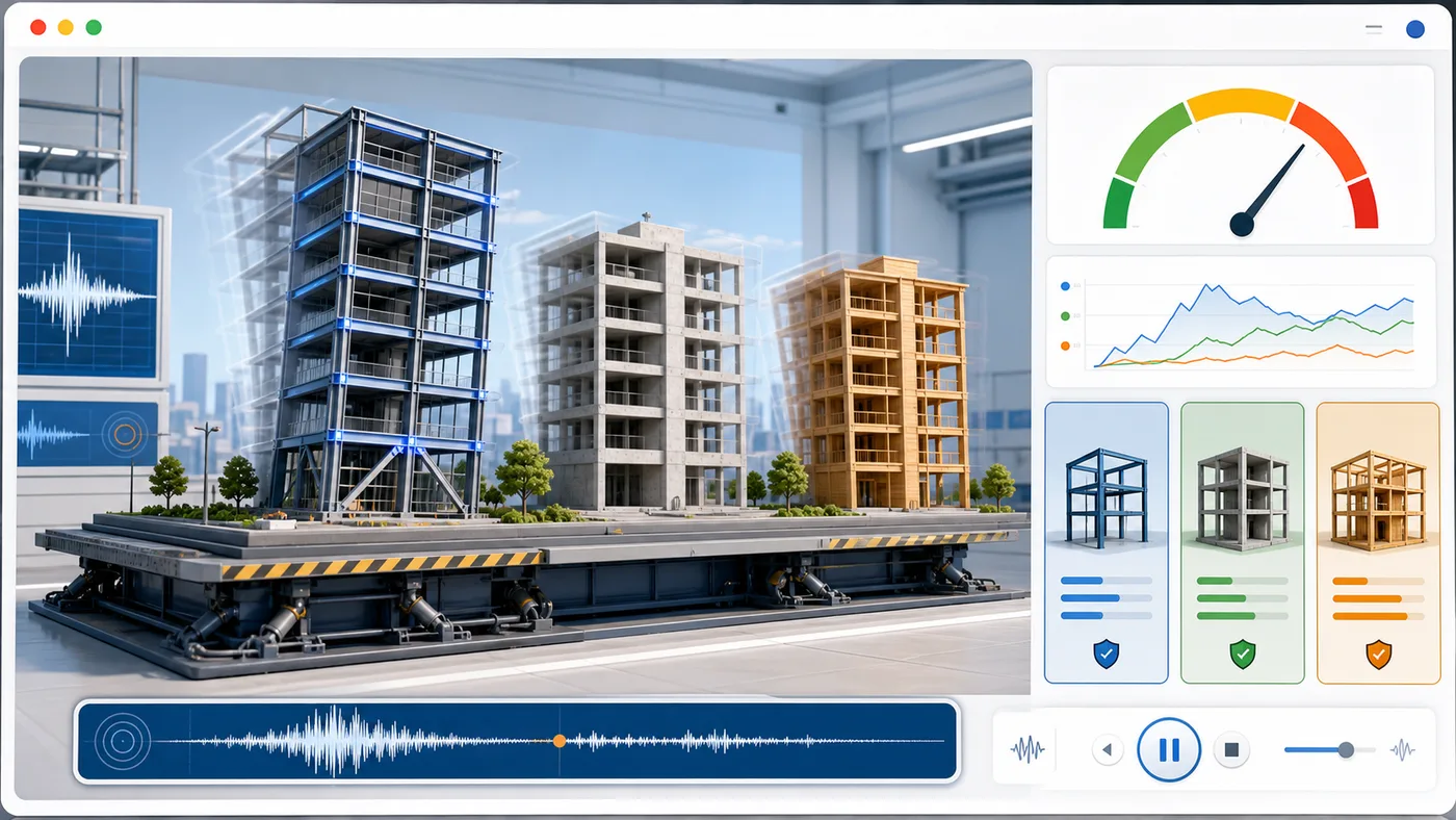
    Earthquake Building Simulator

    Enter building height, floors, material, structure type, earthquake magnitude, and foundation condition to animate sway and compare seismic risk.

    Earthquake Building Simulator preview showing buildings swaying on a shake table with material comparison and risk score
    Open simulator

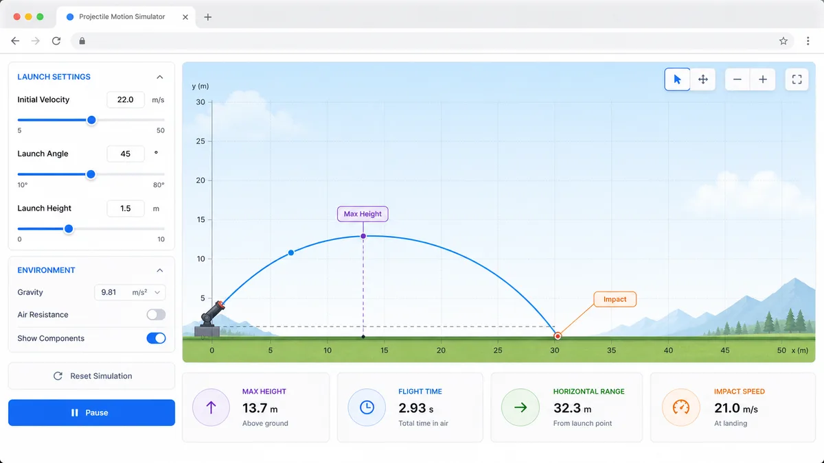
    Projectile Motion Simulator

    Set velocity, angle, height, gravity, and air resistance to compare projectile trajectories and live physics metrics.

    Projectile Motion Simulator preview showing trajectory controls, curve animation, and result metrics
    Open simulator

    Stopping Distance Simulator

    Enter speed, reaction time, weather, road surface, tires, and vehicle type to compare reaction, braking, and total stopping distance.

    Stopping Distance Simulator preview showing braking distance controls, road scenarios, and result metrics
    Open simulator

    Solar Panel Simulator

    Enter location, roof area, panel count, wattage, orientation, tilt, shading, and electricity rate to estimate solar output, savings, and payback.

    Solar Panel Simulator preview showing rooftop panels, energy production, savings, and payback comparison
    Open simulator

    Solar Eclipse Simulator

    Enter a city or coordinates, choose an eclipse event, and estimate local visibility, timing, obscuration, and safety reminders.

    Solar Eclipse Simulator preview showing an eclipse path, local visibility results, timeline, and safety reminders
    Open simulator
    View all simulators

    Thermocouple Simulator FAQ

    Fast answers about Thermocouple Simulator signal trends, cold junction compensation, polarity, wiring faults, and reading limits.

    Is Thermocouple Simulator a calibration tool?

    No. Thermocouple Simulator is for learning and troubleshooting practice. It does not create calibration certificates, lab uncertainty budgets, or safety-critical measurement decisions.

    Does Thermocouple Simulator use exact Type K millivolt tables?

    No. Thermocouple Simulator uses a simplified trend model around common Type K behavior so the relationship between hot junction, cold junction, polarity, and display reading is easy to see.

    Can Thermocouple Simulator diagnose a broken probe?

    No. Thermocouple Simulator can show how an open circuit or loose contact might behave, but it cannot prove that a real probe is damaged.

    Why does Thermocouple Simulator include cold junction compensation?

    A thermocouple signal depends on the temperature difference between junctions. Cold junction compensation lets the instrument account for the cold-end temperature so the displayed value can follow the hot end.

    Does Thermocouple Simulator connect to PLC, DAQ, or real instruments?

    No. Thermocouple Simulator is a pure front-end browser tool. It does not call an API, upload inputs, read real devices, or check instrument compatibility.

    Start Thermocouple Simulator now

    Open Thermocouple Simulator, choose a preset, then adjust hot and cold junction temperatures to see the simplified signal and display trend.

    Switch polarity, compensation, open circuit, loose contact, or copper extension mistakes to practice common thermocouple reading errors without real equipment.

    Thermocouple Simulator is local, offline-capable, and limited to educational trend modeling.